FESTOOL MULTIFUNCTION TABLE MFT 3 MANUAL USER MANUAL FOR THE MULTIFUNCTION TABLE MFT 3 FROM FESTOOL. Tools for the toughest demands
|
|
|
- Alexander Vain
- 2 aastad tagasi
- Vaatused:
Väljavõte
1 FESTOOL MULTIFUNCTION TABLE MFT 3 MANUAL USER MANUAL FOR THE MULTIFUNCTION TABLE MFT 3 FROM FESTOOL Tools for the toughest demands
2
3 3 MULTIFUNCTION TABLE MFT 3 MANUAL FESTOOL MULTIFUNCTION TABLE MFT 3 MANUAL USER MANUAL FOR THE MULTIFUNCTION TABLE MFT 3 FROM FESTOOL
4
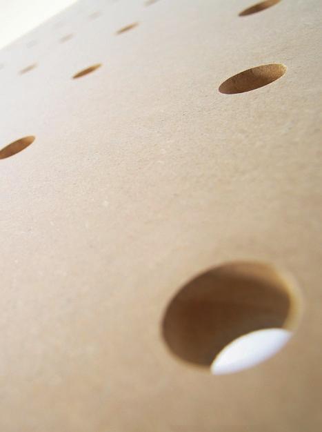
5 »Lots of men have become the tools of their tools.«henry David Thoreau ( ), American writer MULTIFUNCTION TABLE MFT 3 MANUAL INTRODUCTION How a tool manufacturer came to build a table. And why the multifunction table MFT 3 has as much in common with a workbench as a car has with a stage coach. It is a bit unusual to explain a tool philosophy using a table. But this is also the result. The approach is quite obvious: a faultless machine is only one side of the coin. To achieve a perfect result, it is just as important that the workpiece can be processed as perfectly as possible. The worktop, which secures and adjusts the workpiece, is regarded as the heart of the workshop. Although this sounds succinct, if the workpiece has excessive play, the end product will also be a wobbly chair, table or cupboard. A good tool manufacturer organises the woodworking process with the intention of achieving a perfect result and derives everything else from this intended result. Practical experience thus defines the tools. Not vice versa. Festool consistently follows this path. The multifunction table with a 96-mm hole pattern and accessories exactly tuned to one another is the ideal basis for setting up a complete woodworking shop. Its height-adjustable guide rail, surrounding aluminium profile, angle stop with stop slide and additional clamp, hole grid with specially developed clamping elements and clamping screws makes it possible to safely secure workpieces almost independently of size and shape and to process them precisely. As flexible and simple as ever before. You will see that this table is a lot more than just a table: in conjunction with Festool machines it becomes a sophisticated, well thought-out woodworking shop with dimensions 1157 x 773 mm.
6 6 CONTENTS SET-UP AND COMMISSIONING SET-UP OF THE MFT 3 TABLE FRAME INSTALLING GUIDE RAIL SUPPORT INSTALLING GUIDE RAIL INSTALLING ANGLE STOP SAWING SPLINTERGUARD PERFECT SAWING THE MFT 3 AS A CLAMPING AND WORK TABLE CLAMPING WITH SCREW AND LEVER CLAMPS CLAMPING WITH CLAMPING ELEMENTS CLAMPING WITH THE VACUUM CLAMPING SYSTEM VAC SYS SAWING WITH THE MFT 3 PERPENDICULAR CUTS MITRING FRAMES MITRE CUTS WITH SWIVELLED SAW BLADE Compound mitre cuts POCKET OR PLUNGE CUT
7 7 04 ROUTING WITH THE MFT 3 0 MULTIFUNCTION TABLE MFT 3 MANUAL SETTING AND INSTALLING GUIDE STOP ROUTING REBATES GROOVE CUTTING OR DOVETAIL CUTTING CUTTING OUTER AND INNER PROFILES THE COMPACT MODULE SYSTEM CMS Mounting the MFT 3 extension Installation of the CMS modules Working with the CMS sawing module Working with the CMS router module BUILDING A BENCH 76

8 8 INFO THE NEW MFT 3 For some people, simply a table. Practical for laying down tools and papers. Or for making quick notes. Just like all tables. But you expect something different from Festool: Tools and accessories that facilitate your everyday work, developed by experts for practical applications, and which fit into the Festool system perfectly. And all of this in the highest quality. This is why a table from Festool is not simply a table, but arguably the most versatile worktop in the world.

9 MULTIFUNCTION TABLE MFT 3 MANUAL
10 10
11 MULTIFUNCTION TABLE MFT 3 MANUAL SET-UP AND COMMISSIONING SET-UP OF THE MFT 3 TABLE FRAME INSTALLING GUIDE RAIL SUPPORT INSTALLING GUIDE RAIL INSTALLING ANGLE STOP SAWING SPLINTERGUARD PERFECT SAWING

12 12 01 SET-UP AND COMMISSIONING 01 SET-UP AND COMMISSIONING


13 01 SET-UP AND COMMISSIONING READY FOR USE IN NO TIME AT ALL: THE NEW MFT 3 You only need 15 minutes to set up and adjust the MFT 3 and to saw the first board - and it s all so easy! MULTIFUNCTION TABLE MFT 3 MANUAL A ready-fitted table with perforated plate and foldaway legs, guide rail and swivel unit and support unit, angle stop with stop profile, stop slide and additional clamp. This is all it takes to make the MFT 3 arguably the most flexible worktop in the world. Festool is convinced that it is not the quantity of individual parts and assembly instructions several pages long that make a good product, but rather the combination of really necessary components to form a perfect system. Furthermore, using further system components the MFT 3 can be perfectly adapted to your individual requirements and work preferences such that you will no longer wish to dispense with this workshop assistant in future. 1 2 Practical detail: thanks to rubber buffers below the corner profile carriers, the MFT 3 can also be used flat on the floor with folded-in legs for example when installing laminated material or parquet. Ready for use everywhere: the foldaway legs of the MFT 3 allow it to be folded away to save space and for transportation. Ideal for the small workshop and mobile use on site. 01 SET-UP AND COMMISSIONING


14 14 01 SET-UP AND COMMISSIONING 01.1 SET-UP OF THE MFT 3 TABLE FRAME The table frame of the MFT 3 is set up quickly, simply and completely without the need of tools because all parts are preassembled. Already during set-up, the MFT 3 will surprise you with small details that you will appreciate in day-to-day use. The rotary knobs and a detent, for example, ensure that the table legs, whether folded in or out, always remain in the correct position. 1 2 Place the MFT 3 on its side and release the rotary knobs for the foldaway legs. Fold out the legs completely until they engage in position. Then tighten the rotary knobs again firmly. 3 4 TIP: the cross braces (accessories) provide even more stability. When setting up the table, ensure that the cross braces point to the rear. 01 SET-UP AND COMMISSIONING


15 01 SET-UP AND COMMISSIONING The right-hand, front leg is height-adjustable and can be turned to compensate for floor surface irregularities. MULTIFUNCTION TABLE MFT 3 MANUAL 01.2 INSTALLING GUIDE RAIL SUPPORT The swivel unit and the support unit guarantee that the guide rail is firmly secured to the MFT 3 and, at the same time, ensure a fast and uncomplicated change of workpieces. The height adjustment allows the guide rail to be adjusted to different workpiece thicknesses. 1 2 Push the swivel unit at the longitudinal profile of the table with the plastic profile into the table profile. Now you can push the complete unit as far as the stop in the groove and secure with the rotary knob. 01 SET-UP AND COMMISSIONING


16 16 01 SET-UP AND COMMISSIONING 3 4 The support unit is pushed in accordingly at the opposite longitudinal profile and secured. You can use the clamping lever to adjust the height of both units and adapt them exactly to your workpiece thicknesses. 5 The power of the lever tension can be metered exactly by the two Allen screws. 01 SET-UP AND COMMISSIONING


17 01 SET-UP AND COMMISSIONING INSTALLING GUIDE RAIL The guide rail represents, so to speak, the link between the machine and the MFT 3. Plunge cut saws, routers or jigsaws can be guided straight and exactly on the sliding surfaces of the guide rail for precise and neat work results. Additional work precision and safety is provided by the adhesive cushion on the rail: it stops the rail from slipping, keeps it stable while preventing damage to the workpiece surface. MULTIFUNCTION TABLE MFT 3 MANUAL 1 2 Release the two screws in the swivel unit and push the guide rail onto the feather key. Allow the rail to protrude a few centimetres and tighten both screws again firmly. 3 4 On the opposite side, a pin in the support unit secures the rail against slipping. Finally, insert the deflector on the end of the guide rail this prevents the suction hose and cable from catching at the end of the rail. 01 SET-UP AND COMMISSIONING

18 18 INFO The Festool guide rail As the inventor of the guide rail, Festool can look back at over 40 years of experience and, thanks to continuous further development, this patented invention from Festool is unsurpassed up to the present day: the sliding surfaces permit easy and exact guidance of Festool saws and routers. The rubber splinterguard guarantees a perfect cut without splintering. Thanks to the height-adjustable swivel and support unit, workpieces with a height of up to 78 mm can be processed without any problem.

19 MULTIFUNCTION TABLE MFT 3 MANUAL 19


20 20 01 SET-UP AND COMMISSIONING 01.4 INSTALLING ANGLE STOP The ideal supplement to the guide rail is the angle stop, against which the workpiece is safely positioned and precisely aligned. It can be swivelled by 180 and can be used at any point of the surrounding table profile. The stop slide makes exact repeat cuts and even duplicate production possible. Absolute precision is also guaranteed by the additional clamp, with which the sliding fence is secured to the V-groove. 1 2 Insert the angle stop approx. 8 cm away from the guide rail in the table profile and secure it by turning the lower rotary knob. The position of the angle stop on the tabletop can be adjusted flexibly. 3 Now push the sliding fence onto the angle stop. Then tighten the screw to secure the profile against the angle stop. TIP: The sliding fence can also be used vertically. 01 SET-UP AND COMMISSIONING


21 01 SET-UP AND COMMISSIONING MULTIFUNCTION TABLE MFT 3 MANUAL The additional clamp secures the outer end of the sliding fence. It is pushed into the table profile and secured there with the clamping lever. 6 Now push the foldable stop slide into the groove of the sliding fence. It can be secure here at any point with the screw. Prior to all perpendicular cuts, use a large precision angle or a board cut exactly to a right angle to set the angle between the sliding fence and the guide rail. 01 SET-UP AND COMMISSIONING

22 22 01 SET-UP AND COMMISSIONING 01.5 SAWING SPLINTERGUARD A further, well thought-out detail of the Festool guide rail is the splinterguard made of rubber. It has two advantages: on the one hand, it prevents splintering of the wood fibres and guarantees a perfect cut even with veneered boards. No more laborious reworking when cutting with plunge-cut saws! On the other hand, the splinterguard facilitates positioning at the scribe mark because it is easy to see and exact positioning against it is possible this permits rapid completion of angled cuts. 1 Prior to initial use of the guide rail, the splinterguard has to sawn in with the plunge-cut saw. 01 SET-UP AND COMMISSIONING


23 01 SET-UP AND COMMISSIONING MULTIFUNCTION TABLE MFT 3 MANUAL To do this, place an approx. 60 cm wide board under the guide rail and push until it is around 5 mm away from the outer edge of the splinterguard. 4 Adjust the swivel and support exactly to the height of the board. 5 Now place the plunge-cut saw on the guide rail and align the two guidance jaws in the saw table with zero-play to the guide rib of the rail. Set the speed to stage 3 and the cutting depth to approx mm and saw along the complete guide rail once. 6 INFO Splinterguard defective? Only an undamaged splinterguard guarantees faultless, spinter-free cutting edges. You can obtain replacements to match your rail length in the trade. Simply remove the old splinterguard, clean the adhesive surfaces with acetone and stick on the new splinterguard. During the entire sawing process, ensure that both guidance jaws engage in the guide rib of the rail. 01 SET-UP AND COMMISSIONING


24 24 01 SET-UP AND COMMISSIONING 01.6 PERFECT SAWING Festool plunge-cut saws fit perfectly onto the guide rail. This combination makes splinter-free saw cuts on both sides possible: on the one hand, thanks to the guide rail and, on the other hand, due to the attachable plunge-cut saw splinterguard. The slideway lining on the rail ensures that the plunge-cut saw can be guided smoothly and easily. 1 2 Fold up the guide rail and position your workpiece against the sliding fence. Then align the swivel and support unit on the guide rail exactly to the thickness of your workpiece. 3 4 Secure your workpiece on the table using a clamp. Rule of thumb for setting the cutting depth: board thickness plus 5 mm. 01 SET-UP AND COMMISSIONING

.")

25 01 SET-UP AND COMMISSIONING 25 5 For spinter-free cuts on both sides, mount the splinterguard on the plunge-cut saw, lower it onto your workpiece, secure it and saw into it slowly. MULTIFUNCTION TABLE MFT 3 MANUAL 6 The perfect cut, also in long workpieces, is achieved with the retractable trimming attachment, tape measure and the support legs (accessories). INFO MFT 3 TABLE TOP The initial sawing cut in the tabletop has a maximum depth of 5 mm. If the tabletop is worn after a long period of use, it can be reversed and used once again. To do this, simply release the four securing screws, turn the tabletop and screw it back on. 01 SET-UP AND COMMISSIONING
26 26
27 MULTIFUNCTION TABLE MFT 3 MANUAL THE MFT 3 AS A CLAMPING AND WORK TABLE CLAMPING WITH SCREW AND LEVER CLAMPS CLAMPING WITH CLAMPING ELEMENTS CLAMPING WITH THE VACUUM CLAMPING SYSTEM VAC SYS

28 28 02 THE MFT 3 AS A CLAMPING AND WORK TABLE 02 THE MFT 3 AS A CLAMPING AND WORK TABLE

29 02 THE MFT 3 AS A CLAMPING AND WORK TABLE CLAMPING OPTIONS WITH THE MFT 3 MULTIFUNCTION TABLE MFT 3 MANUAL Irrespective of how large or small, angular or round the various clamping options provide maximum security when sanding, planing, bonding or routing. The MFT 3 owes its unique clamping flexibility to the perforated tabletop, the surrounding table profile, the screw and lever clamps and the clamping elements. Further clamping options are provided by combining with the new vacuum clamping system VAC SYS. 02 THE MFT 3 AS A CLAMPING AND WORK TABLE


30 30 02 THE MFT 3 AS A CLAMPING AND WORK TABLE 02.1 Clamping with screw and lever clamps Workpieces clamp quickly and easily with a few flicks of the wrist. In accordance with the Festool system concept, the screw and lever clamps match the hole grid on the tabletop as well as the surrounding profile of the multifunction table. But they also fit from below into the groove of the guide rail, which can thus be secured easily on a door and can be used not only in conjunction with the MFT Two different versions of the clamps are available: lever clamps, or classic screw clamps with different lengths. Pull the lever clamp up as far as it will go and open completely. Now the lower part of the clamp can be inserted in one of the holes in the tabletop. 3 4 For sawing, drilling or routing, the board can project beyond the MFT 3, safely held in position by the clamps. The screw and lever clamps can be inserted from above or from below in the table holes. 02 THE MFT 3 AS A CLAMPING AND WORK TABLE


31 02 THE MFT 3 AS A CLAMPING AND WORK TABLE For vertical clamping, the screw and lever clamps can also be inserted into the surrounding table profile. Now the edges of the workpiece can be worked on comfortably, for example, when drilling holes. MULTIFUNCTION TABLE MFT 3 MANUAL 7 Thanks to the 96-mm hole grid and the surrounding profile of the MFT 3, you can clamp workpieces horizontally as well as vertically. Detailed information on the clamping elements is provided on the following pages. 02 THE MFT 3 AS A CLAMPING AND WORK TABLE


32 32 02 THE MFT 3 AS A CLAMPING AND WORK TABLE 02.2 Clamping with clamping elements To safely secure workpieces, including round ones, on the table for processing, the clamping elements can be inserted in the holes of the 96-mm grid from above and secured from below. They have a decisive advantage over the screw and lever clamps in that the entire surface of the workpiece is free for processing. 1 The clamping elements are inserted in the table holes and secured from below with a rotary knob. They consist of a stop and the movable clamping element with lever handle. 2 3 Place the workpiece between the clamping elements, push the movable clamping head against the edge and pull the lever handle tight to the rear. The workpiece surface can thus be processed comfortably without any interfering clamps. 02 THE MFT 3 AS A CLAMPING AND WORK TABLE


33 02 THE MFT 3 AS A CLAMPING AND WORK TABLE Clamping with the vacuum clamping system VAC SYS The vacuum clamping system VAC SYS allows you to process workpieces in a single work step from all sides. Without time-consuming changing and with radii that permit a 360 rotation and a swivel range of up to 90. The specially shaped plates use the vacuum to clamp the workpiece safely, reliably and in a manner that is gentle on the surface. You can connect the VAC SYS with the MFT 3 by means of an adapter plate and swivel it away downwards when not in use. MULTIFUNCTION TABLE MFT 3 MANUAL Fitting on the MFT The clamping unit of the vacuum clamping system is connected by means of an adapter plate to the MFT 3, which is inserted in the table profile of the MFT 3. In addition, the clamping unit is secured to the adapter plate with four machine screws. The adapter plate is secured with a screw clamp on the perforated plate of the MFT 3. 3 INFO POWERFUL SMOOTH STOP A clamping unit of the vacuum clamping system can clamp workpieces of a size of up to 1 x 1 m and a weight of 30 kg firmly and safely. When not in use, the clamping unit is swivelled under the table to save space and locked there with two rotary knobs. 02 THE MFT 3 AS A CLAMPING AND WORK TABLE
34 34

35 35 MULTIFUNCTION TABLE MFT 3 MANUAL INFO Reliable clamping right down to the finest detail The high-quality plastic of the vacuum plate is so soft and flexible that workpiece surface processing is particularly gentle and even high-gloss polished surfaces remain free of scratches and damage.


36 36 02 THE MFT 3 AS A CLAMPING AND WORK TABLE CHANGING THE VACUUM PLATE 1 2 Four different vacuum plates are available for the different sizes of workpieces. They can be changed quickly and completely tool-free. A Oval vacuum plate, 220 x 60 mm B Round vacuum plate, dia. 515 mm C Narrow vacuum plate, 277 x 32 mm D Oval vacuum plate, 275 x 100 mm CLAMPING AND RELEASING THE WORKPIECES 1 2 The workpieces are safely clamped using vacuum. It is sufficient to place the workpieces with a minimal force on the vacuum plate. You can use the foot valve to aerate the vacuum plate and, at the same time, hold the workpiece with both hands. 02 THE MFT 3 AS A CLAMPING AND WORK TABLE


37 02 THE MFT 3 AS A CLAMPING AND WORK TABLE 37 3 The vacuum plates leave no scratches or damage even on high-gloss polished surfaces. MULTIFUNCTION TABLE MFT 3 MANUAL ROTATING AND SWIVELLING 1 2 The vacuum system allows you to process your workpieces from all sides: vacuum plate rotation by up to 360 and swivelling by up to In vertical position, for example, a board edge can be sanded comfortably. A big advantage in this case is the healthy and ergonomic posture when working on the workpiece. The plate can also be turned together with the workpiece into any position. 02 THE MFT 3 AS A CLAMPING AND WORK TABLE
38 38
39 MULTIFUNCTION TABLE MFT 3 MANUAL SAWING WITH THE MFT 3 PERPENDICULAR CUTS MITRING FRAMES MITRE CUTS WITH SWIVELLED SAW BLADE Compound Mitre Cuts POCKET OR PLUNGE CUT

40 40 03 SAWING WITH THE MFT 3 03 SAWING WITH THE MFT 3

41 03 SAWING WITH THE MFT THE PERFECT CUT MULTIFUNCTION TABLE MFT 3 MANUAL The FESTOOL plunge-cut saw is completely at home when used with the guide rail. With the MFT 3, its accessories and a plunge-cut saw, you are ideally equipped for almost every sawing task. The table, accessories and machine are perfectly tuned to one another and completely in line with the Festool system concept. The plungecut saw can thus be guided exactly and with zero play on the guide rail to produce a straight cut. The sawing depth is set using the depth stop accurate to the millimetre. The attachable splinterguard ensures splinter-free work together with the guide rail you can therefore saw on both sides without splintering. The best conditions for achieving the best possible cutting results. 03 SAWING WITH THE MFT 3

. Then place the workpiece below the guide rail and adjust the guide rail exactly to the thickness of the board.")

.")
42 42 03 SAWING WITH THE MFT Perpendicular cuts The most frequent operations you will perform with the MFT 3 and the plunge-cut saw are perpendicular cuts. Before every perpendicular cut, it is important to first set or check the right angle between the sliding fence and the guide rail (see section 01.4). Then place the workpiece below the guide rail and adjust the guide rail exactly to the thickness of the board. Finally, set the cutting depth of the plungecut saw to the workpiece thickness: nothing can now prevent a perfect cut. 1 2 Use a tape measure to set the stop slide to the desired workpiece length. You can then read off the correct dimension at the splinterguard. Fold up the stop slide and push the board approx. 2 cm beyond the stop slide. TIP: Check the correct cutting depth before starting (rule of thumb: board thickness plus 5 mm). 3 4 Turn round the board, position the cutting edge at the stop slide and fold down the stop slide. TIP: retain the positioning edge. Place the saw on the rail in front of the workpiece and move into the board in plunge-cut position. 03 SAWING WITH THE MFT 3


43 03 SAWING WITH THE MFT Mitring frames A prerequisite for a mitred frame is that the sliding fence is set to exactly 45 and that the frame parts opposite each other have exactly the same length. The foldable stop slide ensures frame parts of equal lengths. The tip in step 7 on the next page shows you how to set the sliding fence to precisely 45. MULTIFUNCTION TABLE MFT 3 MANUAL 1 Set an angle of exactly 45 between the sliding fence and the guide rail. 03 SAWING WITH THE MFT 3


44 44 03 SAWING WITH THE MFT Place the framing timber against the stop and a further piece of timber of the same thickness under the rail as a support. Secure the framing timber with a clamp and set the frame length with a tape measure at the stop slide. 4 5 Place the saw between the support timber and framing timber on the rail and make the mitre cut. Turn the framing timber and position the mitre you just created against the stop slide. 6 7 Then make the second mitre, or saw the framing timber to length. TIP: a 45º mitre can be checked in two different ways: either with a 45º mitre angle or with a 90º precision angle. 03 SAWING WITH THE MFT 3


45 03 SAWING WITH THE MFT Mitre cuts with swivelled saw blade Precise mitre cuts in true register with swivelled saw blade are no problem with the Festool plungecut saw. Thanks to the MFT 3 and guide rail, you are guaranteed absolutely precise and zero-play guidance of the saw. The ingenious swivelling segment of the plunge-cut saw ensures that the splinterguard of the guide rail always follows the saw cut exactly even with an inclined saw blade setting. MULTIFUNCTION TABLE MFT 3 MANUAL 1 2 Release the clamping screws and swivel the saw blade steplessly in any angle between 0 and 45. There is a re-adjustable end guide at 45. Place the plunge-cut saw in front of the workpiece on the guide rail. Press the machine firmly onto the guide rail while you unlock the saw, switch it on and plunge-cut the workpiece. 3 When sawing, ensure that machine advance is uniform and that the saw always remains on the rail with the guide slot. TIP: always use the kickback stop for plunge cuts! 03 SAWING WITH THE MFT 3


46 46 03 SAWING WITH THE MFT COMPOUND mitre cuts A pyramid or a funnel are typical application examples of a compound mitre. Compound mitres are very frequently used in roof framework construction. Compound mitres have two inclinations, whereby one inclination is always determined by the inclination of the saw blade and the other by the inclination of the sliding fence. 1 2 Only if the opposing sides are really identical will all mitre edges also be tight fitting. Ensure therefore that the workpieces are always positioned exactly against the stop and the stop slide (green circle). 3 The cut and repeatability accuracy of the MFT 3 guarantees that all cutting edges and mitres subsequently match each other perfectly. 03 SAWING WITH THE MFT 3

 must always be secured behind")


47 03 SAWING WITH THE MFT Pocket or plunge cut In the case of plunge cuts, such as those required for recessing vent screens, hobs and sinks, the saw blade plunges in at the start of a line and moves back out at the end of the line. In order that the saw blade is not kicked back when it plunges, a kickback stop (illustration 2) must always be secured behind the machine for plunge cutting. MULTIFUNCTION TABLE MFT 3 MANUAL 1 2 The recesses for vent screens can be cut with the MFT 3 and a plunge-cut saw accurate to the millimetre. Insert one kickback stop respectively for the start and end of the cut in the upper groove of the guide rail. Mark the start and end of the cut in order to align to the saw blade teeth to it. 3 4 Lower the saw blade, align to the marking and slide the kickback stop up to the saw and secure it. Make two parallel saw cuts at a distance corresponding to the height of the vent screen. Complete the rest of the saw cut and the narrow sides with the jigsaw. 03 SAWING WITH THE MFT 3
48 48
49 MULTIFUNCTION TABLE MFT 3 MANUAL ROUTING WITH THE MFT 3 SETTING AND INSTALLING GUIDE STOP ROUTING REBATES GROOVE CUTTING OR DOVETAIL CUTTING CUTTING OUTER AND INNER PROFILES

50 50 04 ROUTING WITH THE MFT 3 04 ROUTING ON THE MFT 3 The advantage in this case is based on the system concept: The correct router not only forms a solid working basis, but only guarantees excellent routing results when combined with the correct accessories. 04 ROUTING WITH THE MFT 3

51 04 ROUTING WITH THE MFT 3 51 MULTIFUNCTION TABLE MFT 3 MANUAL Hardly any other cordless tool offers so many application options as the router. It can be used easily to make rebates, grooves and numerous profile versions. But the following also applies here: an exact cutting result is only possible if the router has perfect guidance while cutting. Using the guide rail, the router cannot drift away because it is positively driven on the rail. In this interaction of router and rail, the MFT 3 also plays an important role because, with its stop and stop slide, it guarantees the exact positioning of the workpiece under the guide rail. 04 ROUTING WITH THE MFT 3


52 52 04 ROUTING WITH THE MFT Setting and installing guide stop The rail guides the router accurately, even when the groove does not run parallel to the edge. With the matching adapter, it can be used for this at any time: this link between the router and the guide rail is formed by the guide stop. Before using this accessory, you should check that the stop runs exactly on the guide rib with zero play. Only then can absolutely precise routing results be guaranteed. 1 2 Slide the guide stop onto the rib of the guide rail and adjust the two guidance jaws in the stop with a screwdriver. Insert guide rods in the stop and secure with the screws. Insert the guide stop including the rods in the locating holes on the router. 3 4 Place the router with the stop on the rail and adjust the support such that the machine can no longer tilt to the side. The fine adjustment for the guide stop is another useful accessory. It is simply pushed laterally onto the rod and fixed with two screws. 04 ROUTING WITH THE MFT 3


53 04 ROUTING WITH THE MFT Routing rebates A rebate at the edge of a board is cut with a straight groove cutter. Groove cutters have diameters from 2 mm to approx. 25 mm. The best results are achieved from cutters with a diameter of 20 mm. Because the cutting speed is higher than with smaller router bits because large router bits cut the wood fibres at a flatter angle, thus causing considerably less splintering. MULTIFUNCTION TABLE MFT 3 MANUAL 1 Always cut large rebates in several steps. This not only produces a better cutting pattern, but also conserves the router bit. 2 3 Guide the machine uniformly and freely along the edge. The support at the side of the router effectively prevents lateral tilting of the machine. 04 ROUTING WITH THE MFT 3


.")

54 54 04 ROUTING WITH THE MFT SLIDING DOVETAILS The router together with a dovetail cutter can be used to create a dovetail within a few minutes. Grooves or dovetails can either be cut continuously from one board edge to the other, or end approx. 3 4 cm away from the board edge. For this purpose, a guide limiter (illustration 4) is secured on the guide rail. Before using the dovetail cutter, you should carry out preliminary work with a straight groove cutter and only chamfer the side flanks of the groove with the dovetail cutter. This conserves the very narrow tapered neck on the shank of the cutter and produces a neat, perfectly parallel dovetail. 1 2 Use a pencil to draw the middle of the groove exactly on the wooden board. A dovetail should not run too near to the edge (a distance of cm is ideal). Place the router of the guide rail and shift it until the notch in the router base (arrow) is aligned with the pencil line. This notch always indicates the middle of the router. 3 4 The dovetail should end approx. 3 cm before the edge. Also mark this dimension with the pencil and move the machine so that the line is aligned with the 0 on the scale of the support. Similarly, this position always indicates the middle of the router. Finally, insert a guide limiter on the rail and push up to the guide stop and secure. 04 ROUTING WITH THE MFT 3


55 04 ROUTING WITH THE MFT Adjust the routing depth to a third of the wood thickness and cut a groove up to the guide limiter. The notches in the router base, or the pencil marking, indicate exactly the middle of the groove. MULTIFUNCTION TABLE MFT 3 MANUAL 7 8 Adjust the router laterally with the help of the guide rods and chamfer both straight groove flanks one after the other with the dovetail cutter to 15º. The right-hand groove flank is cut up and left-hand groove is a cut-down operation. Thanks to the compulsory guide on the rail, this is no problem Finally, insert the matching routed dovetail tongue loosely in the groove without glue. For optical reasons, the open end of the groove can be sealed with a dovetail-shaped block. Ensure that you leave sufficient space to allow the wood to work. 04 ROUTING WITH THE MFT 3


56 56 04 ROUTING WITH THE MFT Cutting outer and inner profiles Nicely profiled wooden boards ideally suitable for a breakfast tray or a pot base are a piece of cake for the MFT 3 in conjunction with a router and the matching router bit. For the outer profile, you only have to set the angle stop exactly perpendicular and the stop slide so that the desired lateral profile depth is achieved. Via routing depth at the router, you can then set how deep the profile penetrates the surface. OUTER PROFILE 1 2 The thickness of the profiled cutter clamped in the machine depends on the board thickness. Set the stop and the stop slide, place the board against it and secure with a clamp. TIP: For uniform profiling of all edges, the board must always be firmly in position against the stop slide. 3 4 Always process the front edges of the board first because splintering results to a greater or lesser extent here at the end of board. This is cut away again after routing of the longitudinal edges. 04 ROUTING WITH THE MFT 3

.")


57 04 ROUTING WITH THE MFT 3 57 INNER PROFILE 1 2 MULTIFUNCTION TABLE MFT 3 MANUAL For the inner profile, only cutters that can plunge into the wood can be used. 3 4 The desired sliding path of the router is set by means of a guide limiter in front of and behind the router stop respectively (see circles). Mount the router at the rear guide limiter, set the routing depth, switch on the machine and plunge the router bit into the wood. Push the router immediately forwards until it abuts the front limiter. Step by step all four edges are placed against the stop and the stop slide and the groove is cut. Never allow the router bit to come to a standstill when it is in the timber! 5 If the cutter does not remain too long in one position when plunging and emerging, the groove will be cut successfully without undesirable burn marks. 04 ROUTING WITH THE MFT 3
58 58
59 MULTIFUNCTION TABLE MFT 3 MANUAL THE COMPACT MODULE SYSTEM CMS Mounting the MFT 3 extension Installation of the CMS modules Working with the CMS sawing module Working with the CMS router module


60 60 05 THE COMPACT MODULE SYSTEM CMS 05 OPTIMISED SYSTEM CONNECTION The MFT 3 extension allows you to use all CMS modules for sawing, routing and sanding. To do this, the extension is secured to the MFT 3 and the corresponding CMS module is then inserted in it. BENCH-MOUNTED CIRCULAR SAW A JIGSAW TABLE B Combined with the sawing module and the plunge-cut saw TS 55, the MFT 3 becomes a fully-fledged bench-mounted circular saw with sliding table, which can be mounted on the MFT 3 extension. Thanks to the perfect view of the saw blade and cutting line, curved workpieces can be sawn even more precisely with the jigsaw module carrier. ROUTER BASE C SANDING TABLE D The router module is the ideal supplement when routing with the guide rail on the MFT 3, particularly when working on strips and narrow workpieces. The belt sander module provides the finishing touch to your workpiece edges. It can be used for an excellent finish to both straight and curved edges. 05 THE COMPACT MODULE SYSTEM CMS

61 05 THE COMPACT MODULE SYSTEM CMS 61 MULTIFUNCTION TABLE MFT 3 MANUAL 05 THE COMPACT MODULE SYSTEM CMS


62 62 05 THE COMPACT MODULE SYSTEM CMS 05.1 Mounting the MFT 3 extension The MFT 3 extension permits the use of all modules of the Compact Module System CMS and many of its accessories. To do this, the extension is secured via the Festool V groove on the MFT 3. The corresponding CMS module is then simply inserted in the extension and firmly locked by two screws. This guarantees fast and simple changing of the individual modules. 1 2 As with the MFT 3, the legs of the extension can be folded out and locked with a securing screw. The table lengthener is then attached to the surrounding aluminium profile of the MFT 3. 3 Following this, adjust the height of the table lengthener exactly to the level of the MFT 3 using the screw facing the MFT THE COMPACT MODULE SYSTEM CMS


63 05 THE COMPACT MODULE SYSTEM CMS The clamping screw beside this is used to secure the table lengthener to the aluminium profile. The two height-adjustable legs can be used to readjust the table lengthener in true alignment. MULTIFUNCTION TABLE MFT 3 MANUAL 05.2 Installation of the CMS modules The individual work modules in the CMS allow you to complete many tasks. Sawing with circular saws and jigsaws just as easily as routing or sanding. The individual modules can be exchanged quickly and easily. The built-in machines, however, can be used not only as bench-mounted tools, but also as handheld tools for complete flexibility during work. 1 2 The module plates are inserted on one side in the table lengthener and then lowered. Two screws are used to lock the module safety and securely on the table lengthener. 05 THE COMPACT MODULE SYSTEM CMS


64 64 05 THE COMPACT MODULE SYSTEM CMS 05.3 Working with the CMS sawing module With the guide rail and the MFT 3, you have already become acquainted with a precise cutting option, which, however, reaches its limits when it comes to processing long, narrow workpieces. But the CMS sawing module allows you to install the plunge-cut saw under the module carrier and thus make use of the extended cutting options of a fully-fledged bench-mounted circular saw. If the sawing module is now supplemented by the sliding table available as an accessory, even complicated cuts can be made without any problem. And you always have the choice of using the plunge-cut saw in the sawing module or on the guide rail. 1 2 Ready for action in a few seconds: the bench sawing module is simply inserted in the carrier module of the MFT 3 extension and secured. Your portable circular saw has now become a fully-fledged benchmounted circular saw Installation of the sliding table and use of the angle stop 1 2 The sliding table can be installed in two positions (depending on whether the angle stop is fitted at the front or the rear of the slide). Suspend the sliding table in the V-groove profile and screw on. Adjusting the sliding table height: after releasing the rotary knob, readjust the height as required. The slide angle can also be readjusted. 05 THE COMPACT MODULE SYSTEM CMS


65 05 THE COMPACT MODULE SYSTEM CMS 65 3 Fitting the angle stop: the angle stop can be attached at the front of the slide as shown here, or at the rear. Important: the sliding fence must not rub on the aluminium table! MULTIFUNCTION TABLE MFT 3 MANUAL Mounting and setting the longitudinal stop 1 2 Suspend the angle stop in the profile of the MFT 3. Turn the stop head 90º to the side. 3 Push the sliding fence into the stop head. 05 THE COMPACT MODULE SYSTEM CMS


66 66 05 THE COMPACT MODULE SYSTEM CMS 4 5 On the opposite side, the sliding fence is secured by the additional clamp Sawing at the longitudinal stop Remeasure the parallelism of the sliding fence in relation to the saw blade: use a tape measure to first measure the distance from the stop to the front tooth of the saw blade, and then to the rear tooth. INFO SAFETY NOTE It is essential to use a workpiece holder for workpieces that are narrower than 12 cm. After the desired timber width has been set at the longitudinal stop, the workpiece is simply guided past the sliding fence. 2 3 If particularly narrow strips are to be cut, the aluminium fence must be moved into a flat position at the stop so that it does bump against the chip hood. 05 THE COMPACT MODULE SYSTEM CMS


67 05 THE COMPACT MODULE SYSTEM CMS Sizing and other cuts with the sliding table 1 2 MULTIFUNCTION TABLE MFT 3 MANUAL Trimming board edge: a cut always begins by completely straight sawing of a board edge. When doing this, ensure that the board does not shift during the sawing process. 3 Cutting board to width at the longitudinal stop: the board edge prepared in this manner can now be placed against the longitudinal stop to saw the board exactly to its specified width. 4 Once the board has been cut parallel to a specified width dimension, it must be shortened to the desired length. To do this, a transverse edge is first cut exactly angled to the two longitudinal edges. The foldable stop slide is an extremely useful aid in achieving high repeatability accuracy of cuts. 5 Now the board is placed against the stop slide (green circle) with the angled edge sawn in step 3 and cut to length exactly. TIP: the additional clamp can also be used at the sliding table. 05 THE COMPACT MODULE SYSTEM CMS


68 68 05 THE COMPACT MODULE SYSTEM CMS Mitre cuts with the sliding table 1 2 Conversion of the sliding table: the guide rail of the sliding table must be secured to the MFT 3 extension such that it projects behind the saw blade. Moving the angle stop: the angle stop is suspended at the side profile of the sliding table and secured. 3 4 Setting the inclination: finally, the desired angle is set using the scale on the stop. A pin engages in the scale at the main angles. Mitre cutting the frame: framing timbers for the construction of furniture doors or picture frames can be mitre cut perfectly in true register with the angle stop set to 45º. 5 6 Mitre cutting of board: if board edges are to be mitre sawn, the stop is not swivelled in this case, but rather the saw blade by 45º. Board with double mitre: a precise double mitre cut is always a challenge not only for the machine! Both the saw blade as well as the stop must be swivelled. 05 THE COMPACT MODULE SYSTEM CMS
69 05 THE COMPACT MODULE SYSTEM CMS The most important safety tips for the sawing module Please first read through the Operating Instructions and observe all safety instructions they contain. The mains connector must be disconnected before starting all setting or maintenance work. Only use sharp, undamaged saw blades that have been approved for the machine. Have the saw blades repaired regularly and in good time by a professional sharpening service. Only use saw blades that are suitable for the material to be processed and never exceed the maximum speed specified on the saw blade. MULTIFUNCTION TABLE MFT 3 MANUAL Saw blades made of High Speed Steel (HSS steel) must not be used. Always wear suitable protective equipment such as: ear protectors, protective goggles and breathing protection. Under no circumstances should you wear gloves when sawing. They can caught by the saw blade just as hanging shirt sleeves and can pull your hand into the saw blade. For the same reason, rings and watches must not be worn. Always connect the saw to a suitable and efficient extraction unit. Workpieces that are narrower than 12 cm must always be guided by a workpiece holder. The saw blade must not project more than 10 mm beyond the workpiece. Never remove the riving knife. For hidden saw cuts (e.g. grooves), the riving knife with chip hood is exchanged for a knife without a hood. Never saw fresh or wet timber and check the workpiece for loose knots before sawing. Saw the timber only when guided by a stop (angle or longitudinal stop or sliding table). Never guide the workpiece over the saw table without holding on! Never attempt remove cut off wood from the saw table with your hands when the saw is running. Either use the workpiece holder or wait until the machine has come to a complete standstill. 05 THE COMPACT MODULE SYSTEM CMS

70 70 05 THE COMPACT MODULE SYSTEM CMS 05.4 Working with the CMS router module Maybe you have already tried to profile strips for a picture frame with a hand-guided router? It is precisely in such situations that a table-mounted router is worth its weight in gold. Because the profiles are not only a lot more uniform and look a lot better, but the work is also a lot faster and safer. The CMS modular solution is just right for this task. Of course you can also carry out all other routing work and cut rebates, round edges, radii and shapes Routing techniques with the CMS router module 1 2 At the stop: profiling, rebating and grooving with straight workpieces. At the sliding table: tenon and counterprofile cutting with short workpieces. INFO 3 SAFETY NOTE Everything from the right! At the router base, the workpiece is always pushed from right to left passed the router. This is the only way to cut against the running direction of the router! At the curved router stop: with curved workpieces. 05 THE COMPACT MODULE SYSTEM CMS


71 05 THE COMPACT MODULE SYSTEM CMS Installing the machine in the CMS router module 1 Depending on the routing diameter, the matching spacer ring must also be selected. The gap between the ring and the router should be as small as possible. MULTIFUNCTION TABLE MFT 3 MANUAL 2 3 Place the module used with the upper side on the table. Place the spacer ring in the opening and mount the router. Please observe the Operating Instructions. This centres the router at the same time and now it only has to be secured with the three securing clips. 4 Finally, the plate is turned, inserted in the table opening and locked on the table profile with two screws. 05 THE COMPACT MODULE SYSTEM CMS


 are then guided as near as possible to the router.")


72 72 05 THE COMPACT MODULE SYSTEM CMS The router stop 1 2 Depending on the desired distance to the router, the router stop can be secured at two different positions on the table surface. A wooden strip is perfectly suitable for preliminary adjustment of the position of the stop in relation to the router profile. 3 4 The stop rails (stop jaws) are then guided as near as possible to the router. Finally, adjust the upper and lateral hold-down fixture to the timber thickness and width Rebating and grooving 1 2 Rebating and grooving of strips is more precise and safe on a router base than with a hand-guided router. Always cut out large rebates in several work operations: this conserves the router bit and reduces splintering. Although rebating is also possible with a groove cutter (left), the larger rebating cutter (right) cuts at a higher speed and cuts the fibres at a flatter angle. 05 THE COMPACT MODULE SYSTEM CMS


73 05 THE COMPACT MODULE SYSTEM CMS Pocket cutting 1 If the groove or rebate is not continuous, secure two wooden boards to the stop as starting and starting points. Always include the router (red) in the distance between boards. MULTIFUNCTION TABLE MFT 3 MANUAL 2 For longer workpieces, the boards cannot be secured at the stop. A multiplex extension can help in this case: secure to the stop, secure the boards to it Routing at the sliding table 1 2 To start with, the sliding table must be absolutely parallel to the router stop; at the same time, the stop rail must be exactly perpendicular. Cut the tenon from both sides with a groove cutter. Cut in several operations until the front edge abuts the stop. 05 THE COMPACT MODULE SYSTEM CMS
74 74
75 MULTIFUNCTION TABLE MFT 3 MANUAL BUILDING A BENCH 76

76 76 06 BUILDING A BENCH 06 A BENCH THAT YOU CANNOT BUY Which you can design yourself with a little bit of skill and the correct tool. And if you don t believe it, then you re wrong! This modern bench looks good anywhere in the house. With a few pretty cushions, it becomes a comfortable reading bench; in the hallway, a practical assistant; in summer, protected from the weather, you can even keep it on the patio. The large surfaces accentuate the high-quality wood grain. 06 BUILDING A BENCH


, wood oil and wax A MULTIFUNCTION TABLE MFT 3 MANUAL 1 2 After cutting all")

77 06 BUILDING A BENCH 77 MATERIAL LIST ITEM QTY. NAME DIMENSIONS IN MM MATERIAL A 2 Sides 396 x mm alder 3-layer B 1 Board 1190 x mm alder 3-layer C 2 Seat boards 1190 x mm alder 3-layer D 1 Transverse 1136 x mm alder 3-layer support C A B D ACCESSORIES 8 pce. Dominos 5 x 30, 2 pce. Dominos 10 x 50, 3 pce. Spax screws 5.0 x 80, 20 pce. stainless steel screws 4.0 x 45, wood glue, waterproof (D3), wood oil and wax A MULTIFUNCTION TABLE MFT 3 MANUAL 1 2 After cutting all wooden parts, first make the mitre cuts in the side parts and the board. Mark the sides and board with a joiner s set square on the edge this facilitates subsequent assignment. 3 4 Cut the mitres with the Domino router, four slots in each case for 5 x 30 size Dominos. Place the slightly long transverse support on the underside of the board and mark the exact length of the support. 06 BUILDING A BENCH


78 78 06 BUILDING A BENCH 5 6 Then clamp the transverse support on the side and use the front edge as a stop for the Domino router. With the help of the Domino router strip stop, cut a 10 x 50 size Domino in each of the front edges. 7 8 Round the edges with a router or use the CMS module in the MFT 3 extension. Drill three holes in the transverse support for subsequent fastening of the support to the board with screws Prior to bonding, all inside surfaces of the sides and board must first be smoothed with the ROTEX. First join the board and a side part with glue. Then insert the transverse support. 06 BUILDING A BENCH


79 06 BUILDING A BENCH Finally, insert the other side part with glue and bond everything with the help of straps. When the glue has bonded, the transverse support is fastened to the board with screws. MULTIFUNCTION TABLE MFT 3 MANUAL Using a rebating cutter with ball bearing, cut an 8 mm wide and 8 mm deep rebate in the seat board. Then saw the two 217 mm wide strips for the seat boards out of the wide board Using a counterbore with depth stop, drill the holes for the screws. Locate the seat boards with clamps and secure them with size 4 x 45 screws. 06 BUILDING A BENCH

80 80 06 BUILDING A BENCH Perfect finish The wooden surfaces of the solid 3-layer boards look particularly good if they are simply treated with oil and wax only. First use a flat brush and saturate the wood with the oil. Allow to the oil to dry for approx. 30 minutes and then remove the residual oil from the surface with a clean, lint-free linen cloth. Allow the surface to dry completely overnight and, prior to the second oil application, rub the surface with fine sandpaper (min. grain 280, even better: 400) in direction of the grain. The best wood preservation and finest surface is obtained after a third oil application. If you wish to obtain a velvety gloss, at the end of the process you should treat the entire surface with hard wax. The wax is initially rubbed into the wood in a circular motion and then removed in long strokes in the direction of the grain. Allow the surface to dry well and finally polish it with a leather/sisal brush until an even, velvety gloss is created. INFO SAFETY NOTE Always store oil-soaked cloths in an airtight preserving jar. Otherwise there is a danger of auto-ignition. 06 BUILDING A BENCH
81 81 NOTES MULTIFUNCTION TABLE MFT 3 MANUAL

82 82 MFT 3 The new MFT 3 at a glance MFT 3 EXTENSION GUIDE RAIL

83 83 V-GROOVE CLAMPING ELEMENTS MULTIFUNCTION TABLE MFT 3 MANUAL VACUUM CLAMPING SYSTEM VAC SYS SCREW CLAMP LEVER CLAMP PERFORATED PLATE ADAPTER VAC SYS STOP SLIDE ADDITIONAL CLAMP ANGLE STOP WITH SLIDING FENCE
84 CONTENTS 01 SET-UP AND COMMISSIONING SET-UP OF THE MFT 3 TABLE FRAME INSTALLING GUIDE RAIL SUPPORT INSTALLING GUIDE RAIL INSTALLING ANGLE STOP SAWING SPLINTERGUARD PERFECT SAWING THE MFT 3 AS A CLAMPING AND WORK TABLE CLAMPING WITH SCREW AND LEVER CLAMPS CLAMPING WITH CLAMPING ELEMENTS CLAMPING WITH THE VACUUM CLAMPING SYSTEM VAC SYS SAWING WITH THE MFT PERPENDICULAR CUTS MITRING FRAMES MITRE CUTS WITH SWIVELLED SAW BLADE Compound Mitre CUTS POCKET OR PLUNGE CUT ROUTING WITH THE MFT SETTING AND INSTALLING GUIDE STOP ROUTING REBATES GROOVE CUTTING OR DOVETAIL CUTTING CUTTING OUTER AND INNER PROFILES THE COMPACT MODULE SYSTEM CMS MOUNTING THE MFT 3 EXTENSION INSTALLATION OF THE CMS MODULES WORKING WITH THE CMS SAWING MODULE WORKING WITH THE CMS ROUTER MODULE BUILDING A BENCH 76
Microsoft Word - Loppukilpailu2015_16_tehtavat_viro_1
 Põhikooli matemaatika võistlus Lõppvõistlus reedel 22.1.2016 OSA 1 Lahendamiseks aega 30 min Punkte 20 Selles osas kalkulaatorit ei kasutata. Lühikesed lahendused ja vajalikud joonised teha samale paberile.
Microsoft Word - EVS_ISO_IEC_27001;2014_et_esilehed.doc
 EESTI STANDARD EVS-ISO/IEC 27001:2014 INFOTEHNOLOOGIA Turbemeetodid Infoturbe halduse süsteemid Nõuded Information technology Security techniques Information security management systems Requirements (ISO/IEC
Võrguinverterite valik ja kasutusala päikeseelektrijaamades Robert Mägi insener
 Võrguinverterite valik ja kasutusala päikeseelektrijaamades Robert Mägi insener Robert Mägi o Õpingud: Riga Technical University o Haridus: MSc (Electrical Engineering) MSc (Automatic Telecommunications)
PowerPoint Presentation
 Miks liituda projektiga LIFE Fit for REACH? Karin Viipsi Henkel Balti OÜ (Henkel Makroflex AS) Infopäev ettevõtetele, 09.11.2016 Sisukord Ettevõtte tutvustus Ettevõtte eesmärk projektis Mida on varasemalt
Powakaddy
 Powakaddy PowaKaddy Sport http://www.powakaddy.com/index.php/electric-trolleys/sport.html Elektrilised kärud liitium või tavalise akuga / Electrical trolleys with lithium or acid battery Liitium akuga
(Tõrked ja töökindlus \(2\))
)") Elektriseadmete tõrked ja töökindlus Click to edit Master title style 2016 sügis 2 Prof. Tõnu Lehtla VII-403, tel.6203 700 http://www.ttu.ee/energeetikateaduskond/elektrotehnika-instituut/ Kursuse sisu
Elektriseadmete tõrked ja töökindlus Click to edit Master title style 2016 sügis 2 Prof. Tõnu Lehtla VII-403, tel.6203 700 http://www.ttu.ee/energeetikateaduskond/elektrotehnika-instituut/ Kursuse sisu
REQUEST FOR AN ASSIGNMENT OF LEI (fond) LEI KOODI MÄÄRAMISE TAOTLUS (fond) 1. FUND DATA / FONDI ANDMED: Legal Name / Ametlik nimi: Other Fund Names /
 LEI KOODI MÄÄRAMISE TAOTLUS (fond) 1. FUND DATA / FONDI ANDMED: Legal Name / Ametlik nimi: Other Fund Names /") REQUEST FOR AN ASSIGNMENT OF LEI (fond) LEI KOODI MÄÄRAMISE TAOTLUS (fond) 1. FUND DATA / FONDI ANDMED: Legal Name / Ametlik nimi: Other Fund Names / Fondi teised nimed: Business Register Number / Äriregistri
REQUEST FOR AN ASSIGNMENT OF LEI (fond) LEI KOODI MÄÄRAMISE TAOTLUS (fond) 1. FUND DATA / FONDI ANDMED: Legal Name / Ametlik nimi: Other Fund Names / Fondi teised nimed: Business Register Number / Äriregistri
Sissejuhatus GRADE metoodikasse
 Sissejuhatus GRADE metoodikasse Eriline tänu: Holger Schünemann ja GRADE working group www.gradeworkinggroup.org Kaja-Triin Laisaar TÜ peremeditsiini ja rahvatervishoiu instituut kaja-triin.laisaar@ut.ee
SAF 7 demo paigaldus. 1.Eeldused SAF 7 demo vajab 32- või 64-bitist Windows 7, Window 8, Windows 10, Windows Server 2008 R2, Windows Server 2012, Wind
 SAF 7 demo paigaldus. 1.Eeldused SAF 7 demo vajab 32- või 64-bitist Windows 7, Window 8, Windows 10, Windows Server 2008 R2, Windows Server 2012, Windows Server 2012 R2, Windows Server 2016 või Windows
EESTI STANDARD EVS-EN 1790:1999 This document is a preview generated by EVS Teemärgistusmaterjalid. Kasutusvalmid teekattemärgised Road marking materi
 EESTI STANDARD EVS-EN 1790:1999 Teemärgistusmaterjalid. Kasutusvalmid teekattemärgised Road marking materials - Preformed road markings EESTI STANDARDIKESKUS EESTI STANDARDI EESSÕNA NATIONAL FOREWORD Käesolev
KUULA & KORDA INGLISE KEEL 1
 KUULA & KORDA INGLISE KEEL 1 KUULA JA KORDA Inglise keel 1 Koostanud Kaidi Peets Teksti lugenud Sheila Süda (eesti keel) Michael Haagensen (inglise keel) Kujundanud Kertu Peet OÜ Adelante Koolitus, 2018
EESTI STANDARD EVS-EN :2000 This document is a preview generated by EVS Terastraat ja traattooted piirete valmistamiseks. Osa 4: Terastraadist
 EESTI STANDARD EVS-EN 10223-4:2000 Terastraat ja traattooted piirete valmistamiseks. Osa 4: Terastraadist keevitatud võrkpiire Steel wire and wire products for fences - Part 4: Steel wire welded mesh fencing
Ppt [Read-Only]
![Ppt [Read-Only]](/thumbs/98/138481535.jpg "Ppt [Read-Only]") EL 2020 strateegia eesmärkidest, mis puudutab varajast koolist väljalangemist ja selle vähendamist EL 2020 strateegia eesmärkidest, mis puudutab madala haridustasemega noorte osakaalu vähendamist Madal
EL 2020 strateegia eesmärkidest, mis puudutab varajast koolist väljalangemist ja selle vähendamist EL 2020 strateegia eesmärkidest, mis puudutab madala haridustasemega noorte osakaalu vähendamist Madal
Pealkiri
 Graafilised mudelid ja nende koostamise vahendid MS Visio MYSQL Workbench (DB Designer) ER/Studio Data Architect Sybase PowerDesigner GRAAFILINE MODELLEERIMINE Mudel ja modelleerimine 3 11/3/2015 Matemaatiline
Scanned Image
 EESTI MAAILMAS 21. SAJANDI KÜNNISEL EESTI MAAILMAS 21. SAJANDI KÜNNISEL TARTU ÜLIKOOL EESTI MAAILMAS 21. SAJANDI KÜNNISEL Eesti Vabariigi presidendi Lennart Meri 70. sünnipäevale pühendatud konverentsi
Norrison Ametikudumid, Professional knitwear.cdr
 1. AMETIKUDUMID / PROFESSIONAL KNITWEAR MEESTE VEST / MEN S VEST V- või O-kaelusega sirge joonega paksem või õhem vest. / V- or O-neck straight-lined vest in coarser or finer knitting. V-kaelusega õhem
Erasmus+: Euroopa Noored eraldatud toetused 2015 KA1 NOORTE JA NOORSOOTÖÖTAJATE ÕPIRÄNNE NOORTEVAHETUSED R1 1. taotlusvoor Taotleja Taotluse pealkiri
 Erasmus+: Euroopa Noored eraldatud toetused 2015 KA1 NOORTE JA NOORSOOTÖÖTAJATE ÕPIRÄNNE NOORTEVAHETUSED Loomade Nimel Baltic Animal Rights Gathering 2015 13270 Xploreworld Health in Action 20682 Ahtme
Microsoft PowerPoint _04_20_Teadusest_ATI_tudengitele.pptx
 Tartu Ülikool Jaak Vilo 20. aprill 2009 Jaak Vilo 1 CV Karjääriredel Kuidas tehakse teadust Kuidas mõõta teadust Teadus on lahe saab teha mida tahad saab reisida lõpmatult saab suhelda lõpmatult PhD
Lp. firmajuht!
 Lp. firmajuht! Veebruar, 1998 Meil on meeldiv võimalus kutsuda Teie firmat osalema meditsiinitehnika ja farmaatsiatoodete näitusele Eesti Arstide Päevad 98, mis toimub 24.-25. aprillil 1998. a. Tartus.
Avatud ja läbipaistev e-riik: Ees6 kui rajaleidja Andrus Kaarelson RIA peadirektori asetäitja riigi infosüsteemi alal 10. oktoober 2017
 Avatud ja läbipaistev e-riik: Ees6 kui rajaleidja Andrus Kaarelson RIA peadirektori asetäitja riigi infosüsteemi alal 10. oktoober 2017 Eesti kui rajaleidja e-riigi rajamisel E-teenused meie elu loomulik
Inglise keele ainekava 5.klassile Kuu Õpitulemused Õppesisu Kohustuslik hindamine September 1. Räägib loomadest. Vaba aeg. Animals (Wild life 2. Kuula
 Inglise keele ainekava 5.klassile Kuu Õpitulemused Õppesisu Kohustuslik hindamine September 1. Räägib loomadest. Vaba aeg. Animals (Wild life 2. Kuulab, loeb ja jutustab dialooge and pets) Sõnavara teemadel
SK-3MD
 SK-MD KENWOOD CORPORATION COMPACT DIGITAL AUDIO TEXT B60-57-0 0 MA (J) FE 00 JA 57/0-/JA** Page.07.00, :6 amadobe PageMaker 6.5J/PPC JA JA 6 5 5 6 8 55 56 58 60 6 6 66 67 68 69 69 7 7 76 0 5 8 0 7 8 5
D1003_EXTERIOR_DOOR_UK_SE_NO_DK_FI_EE_LV_LT_RU_02_WEB
 UK SE NO DK FI EE LV LT RU EXTERIOR DOORS INSTALLATION INSTRUCTION MONTERINGSANVISNING YTTERDÖRRAR MONTERINGSANVISNING YTTERDØRER MONTAGEVEJLEDNING YDERDØRE ULKO-OVEN ASENNUSOHJE VÄLISUSTE PAIGALDUSJUHEND
D1003_EXTERIOR_DOOR_UK_SE_NO_DK_FI_EE_LV_LT_RU_02_NEUTRAL_WEB
 UK SE NO DK FI EE LV LT RU EXTERIOR DOORS INSTALLATION INSTRUCTION MONTERINGSANVISNING YTTERDÖRRAR MONTERINGSANVISNING YTTERDØRER MONTAGEVEJLEDNING YDERDØRE ULKO-OVEN ASENNUSOHJE VÄLISUSTE PAIGALDUSJUHEND
E-õppe ajalugu
 Koolituskeskkonnad MTAT.03.142 avaloeng Anne Villems September 2014.a. Põhiterminid Koolituskeskkonnad (Learning environments) IKT hariduses (ICT in education) E-õpe (e-learning) Kaugõpe (distance learning)
rp_ IS_3
 Page 1 of 5 Üldine informatsioon Kummelitee Exemption Flags Toote nimi Exempt from Artwork Exempt from NEP Reporting Country Lipton Brand Name CAMOMILE Product Name Legal Description Country Kummelitee
Rahvusvaheline motokross Baltimere Karikas 2015 Soome Eesti Läti Leedu Kooskõlastanud: EMF-i alajuht; Kinnitanud: EMF peasekretär 1. Aeg ja koht: 18.0
 Rahvusvaheline motokross Baltimere Karikas 2015 Soome Eesti Läti Leedu Kooskõlastanud: EMF-i alajuht; Kinnitanud: EMF peasekretär 1. Aeg ja koht: 18.04.2015, Eesti, Holstre-Nõmme motokeskus. (58 o 18 56.36
Microsoft PowerPoint IntroRiskAnal.ppt
 SISSEJUHATUS RISKIANALÜÜSI VETERINAARSES RAHVATERVISHOIUS Arvo Viltrop EMÜ VLI 1 Kasutatud allikad Woolridge ja Kelly Risk Analysis Course (2000) Vose Consulting Quantitative Risk Assessment for Animal
EST_QIG_TEW-424UB(V3.1.1).cdr
.cdr") Lühike paigaldusjuhend TEW-424UB Sisukord Eesti... 1 1. Enne alustamist... 1 2. Kuidas paigaldada... 2 3. WiFi seadistamine... 4 Tõrkeotsing... 6 Version 12.05.2007 1. Enne alustamist Pakendi sisu TEW-424UB
Lühike paigaldusjuhend TEW-424UB Sisukord Eesti... 1 1. Enne alustamist... 1 2. Kuidas paigaldada... 2 3. WiFi seadistamine... 4 Tõrkeotsing... 6 Version 12.05.2007 1. Enne alustamist Pakendi sisu TEW-424UB
SIDE (IRT 3930) Loeng 10/2011 Võrguteenused Teema - teenused Avo Ots telekommunikatsiooni õppetool, TTÜ raadio- ja sidetehnika inst. T
 Loeng 10/2011 Võrguteenused Teema - teenused Avo Ots telekommunikatsiooni õppetool, TTÜ raadio- ja sidetehnika inst. T") SIDE (IRT 3930) Loeng 10/2011 Võrguteenused Teema - teenused Avo Ots telekommunikatsiooni õppetool, TTÜ raadio- ja sidetehnika inst. avots@lr.ttu.ee Teenused 361 Lairibaühendus Teenused 362 Traffic Classes
SIDE (IRT 3930) Loeng 10/2011 Võrguteenused Teema - teenused Avo Ots telekommunikatsiooni õppetool, TTÜ raadio- ja sidetehnika inst. avots@lr.ttu.ee Teenused 361 Lairibaühendus Teenused 362 Traffic Classes
tallinn arvudes 2003.indd
 15 16 Ilmastik ja keskkond 1. Õhutemperatuur, 2003... 18 2. Päikesepaiste, 2003.... 19 3. Sademed, 2003... 20 4. Keskmine tuule kiirus, 2003.. 21 5. Looduskaitse load, 2003..... 22 6. Õhusaaste paiksetest
Väljaandja: Vabariigi Valitsus Akti liik: välisleping Teksti liik: algtekst Jõustumise kp: Avaldamismärge: RT II 2008, 17, 49 Eesti Vabarii
 Väljaandja: Vabariigi Valitsus Akti liik: välisleping Teksti liik: algtekst Jõustumise kp: 22.04.2008 Avaldamismärge: RT II 2008, 17, 49 Eesti Vabariigi ja Soome Vabariigi viisaküsimustes Soome Vabariigi
Tiitelleht
 Company Data ASFALTSEGUDE TOOTMINE Production of Asphalt Mixtures AVA PDF TOODETUD ASFALTSEGUSID 2011. A. Produced Asphalt Mixtures in 2011 Mixture Type AC surf. bin AC base SMA Other types in tonnes 703
Magnetic MRO
 3D-tehnoloogiad õhusõidukite hoolduses 3D Printimine / Virtuaalreaalsus/ 3D Skänneerimine Pärtel-Peeter Kruuv Interior Workshop supervisor Magnetic MRO Arendused: mis mõjutab, mida rakendada? IT Google
Baltic Retail Forum 2019 Baltic Retail Forum on konverents jaekaubanduse juhtidele. Arutleme uueneva tehnoloogia arengusuundade üle, analüüsime
 Baltic Retail Forum 2019 Baltic Retail Forum 2019 - on konverents jaekaubanduse juhtidele. Arutleme uueneva tehnoloogia arengusuundade üle, analüüsime kaubandussektori väljavaateid, otsime õigeid vastuseid
Väljaandja: Vabariigi Valitsus Akti liik: välisleping Teksti liik: algtekst Jõustumise kp: Avaldamismärge: RT II 2009, 22, 55 Eesti Vabarii
 Väljaandja: Vabariigi Valitsus Akti liik: välisleping Teksti liik: algtekst Jõustumise kp: 06.08.2009 Avaldamismärge: RT II 2009, 22, 55 Eesti Vabariigi valitsuse ja Läti Vabariigi valitsuse toornafta
SQL
 SQL Teine loeng Mõtelda CREATE TABLE ( { INTEGER VARCHAR(10)} [ NOT NULL] ); Standard SQL-86 (ANSI X3.135-1986), ISO võttis üle 1987 SQL-89 (ANSIX3.135-1989) SQL-92 (ISO/IEC 9075:1992)
CSS juhend
 Lehekülg 1/5 31.12.2012 21:11 CSS (Cascading Style Sheets) CSS on keel kujunduse loomiseks veebidokumentidele. Tänases praktikumis rakendame CSS-i veebidokumendile, kasutades programmi Dreamweaver. Töö
Slide 1
 TÖÖTUBA: ÕPIRÄNDE TUNNISTUSE TÄITMINE Margit Paakspuu 5163 Töötoa ülesehitus 1. Kellele ja milleks me õpirände tunnistusi väljastame? 2. Õpirände tunnistuse väljastamise protseduur 3. Õpirände tunnistuse
Microsoft PowerPoint - RRand_MEMS.ppt
 MEMS sensorid Rait Rand 1 Sissejuhatus MEMS MEMS : Micro-electromechanical systems 1974.a. rõhusensor masstoodangus 1988.a. mikromehhaanika ühendati elektroonikaga Süsteemina Sensorsüsteemid Aktuaatorsüsteemid
Kehtiv alates Vormi TSD lisa 3 Applicable from Annex 3 of Form 3 Unofficial translation Maksu- ja Tolliamet Estonian Tax and Cus
 Kehtiv alates 01.01.2018 Vormi TSD lisa 3 Applicable from 01.01.2018 Annex 3 of Form 3 Unofficial translation Maksu- ja Tolliamet Estonian Tax and Customs Board MITTERESIDENDIST JURIIDILISE ISIKU PÜSIVAST
Funktsionaalne Programmeerimine
 Kõrvalefektid ja Haskell Kõik senised programmid on olnud ilma kõrvalefektideta; so. puhtalt funktsionaalsed. Programmi täitmise ainsaks efektiks on tema väartus. Osade ülesannete jaoks on kõrvalefektid
III OSA. RAADIOSAGEDUSALA 3600 MHz 1000 GHz Rahvusvahelise Telekommunikatsiooni Liidu konventsiooni ja põhikirja täiendavate raadioeeskirjadega määrat
 III OSA. RAADIOSAGEDUSALA 3600 MHz 1000 GHz Rahvusvahelise Telekommunikatsiooni Liidu konventsiooni ja põhikirja täiendavate raadioeeskirjadega määratud raadiosagedusala kasutusrežiim ja otstarve 3600
Pealkiri
 Andmebaasid (6EAP) I praktikum Mida praktikumides tehakse? Õpitakse SQL i Tehakse andmebaas ope (igas praktikumis natuke, kuni lõpuks saab valmis) Tehakse andmebaas edu (kui ope on valmis, tehakse edu,
EST_Web_QIG_TU-P1284.cdr
 Lühike paigaldusjuhend TU-P1284 Table Sisukord of Contents Eesti... 1. Enne alustamist... 2. Riistvara paigaldamine... 3. Draiveri paigaldamine... 4. Paigaldamise kontrollimine... 1 1 2 3 4 Tõrkeotsing...
Kuidas, kus ja milleks me kujundame poliitikaid Kuidas mõjutavad meid poliitikad ja instrumendid Euroopa Liidu ja riigi tasandil Heli Laarmann Sotsiaa
 Kuidas, kus ja milleks me kujundame poliitikaid Kuidas mõjutavad meid poliitikad ja instrumendid Euroopa Liidu ja riigi tasandil Heli Laarmann Sotsiaalministeerium Rahvatervise osakond 15.06.2018 Mis on
Väljaandja: Riigikogu Akti liik: välisleping Teksti liik: algtekst Avaldamismärge: RT II 1999, 15, 92 Kohtulikult karistatud isikute üleandmise Euroop
 Väljaandja: Riigikogu Akti liik: välisleping Teksti liik: algtekst Avaldamismärge: RT II 1999, 15, 92 Kohtulikult karistatud isikute üleandmise Euroopa konventsiooni lisaprotokoll (õ) 27.02.2009 Lisaprotokolli
Language technology resources for Estonian text summarization Kaili Müürisep University of Tartu Institute of Computer Science
 Language technology resources for Estonian text summarization Kaili Müürisep University of Tartu Institute of Computer Science Outline Estonian language resources First experiment for summarization EstSum
Microsoft Word - EVS-EN _ pdfMachine from Broadgun Software, a great PDF writer utility!
 EESTI STANDARD KONSTRUKTSIOONITERASEST KUUMVALTSITUD TOOTED Osa 1: Üldised tehnilised tarnetingimused Hot rolled products of structural steels Part 1: General technical delivery conditions EESTI STANDARDIKESKUS
Tartu Ülikool
 Tartu Ülikool Code coverage Referaat Koostaja: Rando Mihkelsaar Tartu 2005 Sissejuhatus Inglise keelne väljend Code coverage tähendab eesti keeles otse tõlgituna koodi kaetust. Lahti seletatuna näitab
Microsoft Word - EVS_ISO_3574;2008_esilehed
 EESTI STANDARD EVS-ISO 3574:2010 KÜLMALT MÕÕTUVALTSITUD ÜLDTÖÖSTLUSLIKU KVALITEEDIGA JA TÕMBEKVALITEEDIGA SÜSINIKTERASLEHT Cold-reduced carbon steel sheet of commercial and drawing qualities EVS-ISO 3574:2010
Microsoft Word - EVS_ISO_31000;2010_et_esilehed
 EESTI STANDARD EVS-ISO RISKIJUHTIMINE Põhimõtted ja juhised Risk management Principles and guidelines EVS-ISO EESTI STANDARDI EESSÕNA NATIONAL FOREWORD Käesolev Eesti standard EVS-ISO Riskijuhtimine. Põhimõtted
Microsoft PowerPoint - CNT_konkurss [Compatibility Mode]
![Microsoft PowerPoint - CNT_konkurss [Compatibility Mode]](/thumbs/88/116681768.jpg "Microsoft PowerPoint - CNT_konkurss [Compatibility Mode]") Sissejuhatus süsinik- nanotorude maailma Kristel Kosk Juhendaja: Jevgeni Šulga, Tartu Ülikooli Füüsika Instituut Eesti Nanotehnoloogiate Arenduskeskus 1 1. Sissejuhatus nanomaailma 2. Süsinik 3. Süsinik-nanotorud
Sissejuhatus süsinik- nanotorude maailma Kristel Kosk Juhendaja: Jevgeni Šulga, Tartu Ülikooli Füüsika Instituut Eesti Nanotehnoloogiate Arenduskeskus 1 1. Sissejuhatus nanomaailma 2. Süsinik 3. Süsinik-nanotorud
Väljaandja: Vabariigi Valitsus Akti liik: välisleping Teksti liik: algtekst Jõustumise kp: Avaldamismärge: RT II 2008, 29, 84 Eesti Vabarii
 Väljaandja: Vabariigi Valitsus Akti liik: välisleping Teksti liik: algtekst Jõustumise kp: 01.08.2008 Avaldamismärge: RT II 2008, 29, 84 Eesti Vabariigi ja Soome Vabariigi viisaküsimustes Iraani Islamivabariigis
PowerPoint Presentation
 Marek Alliksoo Export Sales Manager 01 November 2018 Targa linna lahendused linnaplaneerimises Tark linn Tark asjade internet (Tark Pilv) Tark automatiseeritus Tark energia Tark juhtimine Tark kodanik
Microsoft Word - C035736e.doc
 EESTI STANDARD Süsteemi- ja tarkvaratehnika Süsteemide ja tarkvara kvaliteedinõuded ja kvaliteedi hindamine (SQuaRE) Andmekvaliteedi mudel Software engineering Software product Quality Requirements and
Microsoft Word - Referaat.docx
 Tartu Ülikool Andmeturve Referaat teemal: CVE-2016-1499 Koostaja: Sander Sats Kursus: Informaatika Tartu 2016 Sissejuhatus Käesolev referaat on kirjutatud seoses Tartu Ülikooli kursuse MTAT.03.134 Andmeturve
EESTI STANDARD EVS-ISO/IEC 25021:2014 This document is a preview generated by EVS SÜSTEEMI- JA TARKVARATEHNIKA Süsteemide ja tarkvara kvaliteedinõuded
 EESTI STANDARD SÜSTEEMI- JA TARKVARATEHNIKA Süsteemide ja tarkvara kvaliteedinõuded ja kvaliteedi hindamine (SQuaRE) Kvaliteedinäitajate elemendid Systems and software engineering Systems and software
key_Opet_A4.indd
 You are what you wear Õppetsükli sisu: 7A Clothes Talk 7B Fashion day at the English Café 7C High noon Grammatika: Sõnade järjekord Tsükli teema: Milliseid riideid sa kannad ja miks? Key Talk: Viisakusväljendeid
Tuletõkkeklapi eelseadistamine Seadme on konstrueerinud ja eelseadistanud tootja, seadme töö sõltub korralikust paigaldusest ja reguleerimisest. Trans
 Tuletõkkeklapi eelseadistamine Seadme on konstrueerinud ja eelseadistanud tootja, seadme töö sõltub korralikust paigaldusest ja reguleerimisest. Transport ja ladustamine Klapid tuleb transportida veokitega,